|
||||||||||||||||||||||||||||||||||||||||||||||||||||||||||
|---|---|---|---|---|---|---|---|---|---|---|---|---|---|---|---|---|---|---|---|---|---|---|---|---|---|---|---|---|---|---|---|---|---|---|---|---|---|---|---|---|---|---|---|---|---|---|---|---|---|---|---|---|---|---|---|---|---|---|
|
top
top
top
top
top
top
top
top |
|
ˆ
top
top
top |
||||||||||||||||||||||||||||||||||||||||||||||||||||||||
|
40 |
40+110+570=720 |
|||||||||||||||||||||||||||||||||||||||||||||||||||||||||
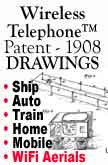
Attention
all major Wireless Telephone®™©
Companies and WiTEL - Wi-Fi Broadcasters. The Next
Century of the Wireless Telephone®™©
is waiting for you! Get Ready for 2009 -- the 101st
year of the Wireless Telephone®™©
Organization . . . See WiTEL.org . . .
" top top top top top top top top 01
/ "The Patent's of Nathan B.
Stubblefield •
• [080512]
PATENT - 1908: May 12, 1908; WIRELESS
TELEPHONE - No. 887,357, Patented May 12,
1908 - UNITED STATES PATENT OFFICE. NATHAN
B. STUBBLEFIELD, OF MURRAY KENTUCKY,
ASSIGNOR OF TWELVE AND ONE-HALF
ONE-HUNDREDTHS TO CONN LINN, FIVE
ONE-HUNDREDTHS TO R. DOWNS, FIVE
ONE-HUNDREDTHS TO B.F. SCHROADER, FIVE
ONE-HUNDREDTHS TO GEORGE C. McLARIN, FIVE
ONE-HUNDREDTHS TO JOHN P. McELRATH, TWO
AND ONE-HALF ONE HUNDREDTHS TO JEFF D.
ROULETT, AND ONE-TWENTIETH TO SAMUEL E.
BYNUM, ALL OF MURRAY, KENTUCKY. - WIRELESS
TELEPHONE. No. 887,357 Patented May 12,
1908. To all
whom it may
concern: SEE
COPY OF ORIGINAL FRONT PAGE
MORE
/ RELATED STORIES AND
IMAGES Part
02 / THE FIGURES IN THE DRAWINGS (continued) 03.
/ SPECIFICATIONS OF AERIALS OR ANTENNA'S ByLine
/ Source
of Study More
Articles • Converging
News 282006 / TeleCom BuyOuts, Spinoffs and Asset
Seizure Boom •
NBS100
Study - NBS - 1908 Patent Break
down •
Page
00 - Home - SMART DAAF BOYS
INDEX • See
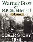
Warner Bros Mag - 1972 CLICK TO GO DIRECTLY
TO" We Preserve The
Moment • NBS
Patent •
NBS100
Study - NBS - 1908 Patent Break
down 110
PATENTS CLICK
TO GO DIRECTLY TO" Google
KudoAds
Dear Editor LookRadio • 120 PIXELS 3
columns top top top 40 40+110+570=720
![]()
![]()
![]()
![]()
Movies
![]()
CLICK
S90
Google
IMAGES
GOOGLE![]()
![]()
![]()
ˆ
![]()
ˆ
ˆ
ˆ
ˆ
ˆ
ˆ
ˆ
WIRELESS TELEPHONE™ PATENT - 1908
Study
of FCC
Summary
Gov.
Control
Legal
Opinions
Acknowledgments
"Wireless"
•
NBS100
FTC STUDY - THE Red Flags
Rule
"ID
Theft Prevention" - for the WiTEL®™©
Industry"

•
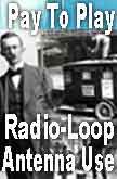
PATENT
PREFACE AND INTRODUCTION OF
OWNERS
•
• NBS
PATENT
DRAWINGS
•
•
AERIAL
- ANTENNA
SPECIFICATIONS
•
THE
BROADCASTING SYSTEM and HOW IT
WORKS
Excerpts
from the President's Edition of the Smart
Daaf Boys, Vol. I - The Inventors of Radio
& Television and the Life Style of
Nathan B. Stubblefield - with Documents -
The
SMART-DAAF BOYS"™ The True Story
About The Inventors of Radio and
Television ©1993-2006
(Library
of Congress Catalog Card #93-060451 / ISBN
1-883644-00-3)
By
Troy Cory-Stubblefield and Josie
Cory
Smart
Daaf Boys - Products
•
• Be
it known that I, NATHAN B. STUBBLEFIELD, a
citizen of the United States, residing at
Murray, in the county of Calloway and
State of Kentucky, have invented a new and
useful Wireless Telephone, of which the
following is a
specification.
•
• The
present invention relates to means for
electrically transmitting signals from one
point to another without the use of
connecting wires, and more particularly
comprehending means for securing
telephonic communication between moving
vehicles and way
stations.
•
• The
principal object of the invention is to
provide simple and practical means of a
novel nature whereby clear and audible
communication can be established, and
means being simple and of a character that
will permit certain of the station
mechanisms to be small and compact.
CONTINUED
•
NBS
Wireless Telephone
WiFi Patents
•
• In
the accompanying drawings: -- Figure 1 is a
perspective view, showing means for establishing
communication between a vessel and a shore station.
Fig. 2 is a diagrammatic view of the mechanism
mounted on the boat. Fig. 3 is a cross sectional
view on an enlarged scale of the shore coil. Fig. 4
is a perspective view of a road-way, showing a
system for establishing communication between road
vehicles and a way-station, the latter being
illustrated diagrammatically. Fig. 5 is a detail
view of a vehicle equipped with one of the
instruments, which is shown diagrammatically. Fig.
6 is a perspective view showing the system applied
to a railway for establishing communication between
a moving train and a way-station. Fig. 7 is a
sectional view through a car showing in diagram the
car mechanism illustrated in Fig.
6.
•
•Similar
reference numerals designate corresponding parts in
all the figures of the
drawings.
•
•Referring
to the embodiment illustrated in Figs. 1, 2 and 3,
a water-way 8 is disclosed, upon which a vessel 9
operates. Surrounding the path of travel of the
vessel, and preferably elevated on poles 10, is a
coil 11 of considerable magnitude. This coil, as
shown in Fig. 3, consists of an outer casing 12,
within which is placed a conducting wire comprising
a plurality of convolutions 13, each of which is
insulated from the other. The terminals 14 of this
coil extend to a suitable way-station, and at the
station is located a powerful source of electrical
energy 15, to which is connected by a suitable wire
16, an electrically operated transmitter 17. The
battery or other source of electricity has a
connection 18 with one of the leads 14. A receiver
19 of the ordinary type has a connection with the
same lead 14, to which the battery is connected,
and both the receiver and transmitter have
connections 21 with the contacts of a switch 22.
This switch has suitable means, as for instance, a
spring 23, which normally maintains the receiver in
circuit with the coil 11, as will be evident by
reference to Fig. 1, but if the switch is thrown to
break the circuit, it will then cut in the source
of electrical energy 15 and the transmitter
17.
•
•An
outfit similar to the above, is located on the
vehicle or boat 9, but the coil 24 thereof, shown
in Fig. 2, is much smaller. As further illustrated
in said figure, the mechanism mounted on the boat,
consists of a transmitter 25, and a battery or
other source of electrical energy 26 electrically
connected, as shown at 27 and having a connection
28 with one of the leads of the coil. The receiver
29 also has a connection 30 with said lead. A
switch 31 is connected to the other lead, and is
normally held in a position by a spring 32 to
maintain a closed circuit through the receiver 29
and the coil, though it may be moved to cut out
said receiver and close the circuit through the
coil, the source of electrical energy and the
transmitter.
•
•In
this system, if it is desired to transmit from one
station, as for instance, the shore-station, the
switch 22 is moved downwardly to cut out the
receiver and throw in the transmitter and source of
electrical energy, while the operator upon the boat
or vehicle leaving the mechanism in the condition
shown in Fig. 2, holds the receiver 29 to his ear.
If therefore the operator at the shore-station uses
the transmitter in the ordinary manner, a varying
current corresponding to that passing through the
coil of great magnitude 11, will be induced in the
coil 24, and the speech or other sounds will thus
be transmitted to the operator on the boat. By
reversing the arrangement, speech may be
transmitted from the boat to the shore station.
CLICK
To find out why the FIGURES IN EACH PATENT DRAWING
HEREIN ARE CONSISTENT WITH EACH
OTHER
•
•The
use of coils for both stations, each coil
consisting of a plurality of convolutions has been
found by experience to be of the utmost value, and
furthermore experience has demonstrated that the
employment of coils of different magnitudes is of
great importance, for it has been found that while
two small coils can be used to transmit but a short
distance, if one large coil of the character set
forth is employed, the other may be very small, and
speech or sounds can be transmitted comparatively
great distances form one to the other. These sounds
are clearly
audible.
•
•The
structure disclosed in Figs. 4 and 5 is of the same
general character. A road-way 32 is disclosed
surrounded by a coil 33 of great magnitude that is
supported on suitable poles 34. The way-station 35
consists of a transmitter 36, a source of
electrical energy 37 connected thereto, a receiver
38, and a switch 39, whereby the receiver or the
transmitter and source of electrical energy can be
thrown into circuit with the coil 33. The vehicles
40, which operate on the roadway, are provided with
smaller coils 41 and instruments consisting of
receivers 42, transmitters 43, sources of
electrical energy 44 and switches 45 all arranged
in the manner already described. In a system of
this kind, it will be evident that the occupant of
one vehicle may telephone to the home or
way-station, and the message can be transmitted to
another vehicle. Thus it will be evident that
communication can be established between two moving
vehicles or between a way-station and any vehicle
desired which is within the range of the home - or
way-station. The system is also capable of use in
connection with railways, and in Figs. 6 and 7,
such a system is disclosed in connection
there-with. A comparatively great coil 46 is
supported on opposite sides of the railway 47 by
poles 48 and a station 49 has a receiver 50 and a
transmitter 51, a source of electrical energy 52
and a switch 53, the last mentioned being employed
for throwing either the receiver or the transmitter
and source of electrical energy into closed circuit
with the coil 46. One or more cars of a railway
train is equipped with an outfit consisting of a
coil 54, a receiver 55, a transmitter 56, a source
of electrical energy 57, and a switch 58 for
throwing either the receiver or the transmitter and
source of electrical energy into circuit with the
coil 54. It will be evident that the operation of
these two last described systems are substantially
the same as that first set forth, and no extended
description thereof is believed to be
necessary.
•
•From the
foregoing, it is thought that the construction,
operation, and many advantages of the herein
described invention will be apparent to those
skilled in the art, without further description,
and it will be understood that various changes in
the size, shape, proportion, and minor details of
construction, may be resorted to without departing
from the spirit or sacrificing any of the
advantages of the invention. Having thus fully
described my invention, what I claim as new, and
desire to secure by Letters Patent, is:
/
THE NBS
WIRELESS TELEPHONE SYSTEM
•
•1. In a
system of the character described, the combination
with a vehicle, of a comparatively small coil of
conducting material mounted thereon, electrical
transmitting and receiving mechanism including a
source of electrical energy connected to the small
coil and carried by the vehicle, a stationary
aerial coil of much greater magnitude than the
small coil having its opposite stretches or sides
extending along the opposite sides of the path of
travel of the vehicle and elevated above the same
and above the vehicle coil, and electrical
transmitting and receiving mechanism connected to
the greater coil and including a source of heavy
electrical current.
• •2.
In a system of the character described, the
combination with a vehicle, of a coil of conducting
material mounted thereon, electrical transmitting
mechanism, a source of electrical energy connected
thereto, receiving mechanism, means for connecting
either the transmitting mechanism and source of
electrical energy or the receiving mechanism to the
coil, a stationary coil of greater magnitude
surrounding the path of travel of the vehicle and
comprising a plurality of convolutions of
conducting material, the different convolutions
being insulated one from the other, means for
supporting the coil in an elevated position,
electrical transmitting mechanism, a source of
great electrical energy connected to said
transmitting mechanism, electrical receiving
mechanism, and means for electrically connecting
either the transmitting mechanism and source of
electrical energy or the receiving mechanism to the
said coil of greater
magnitude.
• •3.
Means for communicating between a plurality of
stations which consists of an aerial electrical
coil of great magnitude, means for supporting the
said coil, a station electrically connected to the
great coil and comprising transmitting and
receiving mechanism that includes a source of heavy
electrical energy, and a plurality of other
separate stations simultaneously in co-acting
relation with the aerial coil, each of said latter
stations comprising a coil of conducting material
spaced from but in co-acting relation with said
great coil and below the same, and transmitting and
receiving mechanism connected to said other coil
and including a source of electrical
energy.
• •4.
Means for communicating between a plurality of
stations which consists of an serial coil of
conducting material of great magnitude,
transmitting and receiving mechanism connected to
said aerial coil and including a source of heavy
electrical energy, a plurality of vehicles movable
between the opposite sides or stretches of the
great coil, coils carried by said vehicles and
disposed within the field of action of the serial
coil, and transmitting and receiving mechanism
mounted on each vehicle and including a source of
electrical energy.
• •In
testimony, that I claim the foregoing as my own, I
have hereto affixed my signature in the presence of
two witnesses.
•
•NATHAN B.
STUBBLEFIELD
•
•Witnesses:
• •
J.P. McELRATH,
•
•J.H.
COLEMAN
• Page
00 - MAIN - PATENT INDEX
PAGE
• Page
01 - Ship to
Shore
•
Wireless Telephone Patent • U.S. Patent Office
Drawing Page 01 - Ship To Shore • Nathan
Stubblefield - 1908 / Patent: No 887,357 - MORE
STORY
•
Page
02 - Auto to Land-lines
•
TVInews -110 Wireless Telephone Patent - •
U.S. Patent Office Drawing Page 02 - Automobile
Vehicles • Nathan Stubblefield - 1908 /
Patent: No 887,357 - MORE
STORY
•
Page
03 - Train / •
Wireless Telephone Patent - Nathan Stubblefield -
1908 / Patent: No 887,357 • U.S. Patent Office
Drawing Page 03 - Railroad Train - MORE
STORY
•
Page
04 - T01
• Wireless Telephone Patent - Nathan
Stubblefield - 1908 / Patent: No 887,357 •
U.S. Patent Office Text Front Page 01 - MORE
STORY
•
Page
05 - T02
• TVInews -110 Wireless Telephone Patent -
Nathan Stubblefield - 1908 / Patent: No 887,357
• U.S. Patent Office Text Page 02 - LAND
VEHICLES - MORE
STORY
•
Page
06 - T03
• TVInews -110 Wireless Telephone Patent -
Nathan Stubblefield - 1908 / Patent: No 887,357
• U.S. Patent Office Text Page 03 - LAND
VEHICLES - MORE STORY
•
Page
00
Index
•
Page
01 NBStory
•
Page
02 NBStory
•
Page
03 NBStory
•
Page
04 NBStory
•
Page
05 NBStory
US Patent Office To See NBS - 1908 Patent
FRONT
PAGE -
TEXT
PAGE
02 -
TEXT
PAGE
03 -
TEXT
Drawing
01 -
Ship
Drawing
02 -
Auto
Drawing
03 -
Train
///
Josie
Cory
Publisher/Editor
TVI Magazine

GOOGLE
KudoADS
We Preserve The Moment
Yes90
tviNews S90
110 NBS100
/ NBS100
TELECOM STUDY - "P" Wireless
Telephone Patent
- Nathan Stubblefield -
1908
•
Patent No. 887,357
/
Feature
Story / • NBS100reportPatent.htm
/
Smart90, lookradio, nbs100, tvimagazine, vratv,
xingtv, Ddiaries, Soulfind, nbstubblefield,
congming90, chinaexpo, vralogo, Look Radio, China
Expo, Soul Find, s90tv, wifi90, dv90, nbs 100,
Josie Cory, Publisher, Troy Cory, ePublisher, Troy
Cory-Stubblefield /
Kudoads,
Photo Image665, Movies troy cory show
duration:medium:free - 4
min
- Television With No Borders
How
Do We Do Business?
Tel
323 462-1099
SEND
E-MAIL
Return
ˆ
To
Top
top
Study
•NBS
"P" Patent Study
Go
To Next Page 01 - Ship
•
TVInews -110 Wireless Telephone Patent
-
Nathan Stubblefield - 1908 / Patent: No
887,357
• U.S. Patent Office Drawings •
Written
•
See Patents
•
Page
00 -
Home
• Page
00 -
MAIN
• Page
01 -
Ship
• Page
02 -
Auto
• Page
03 -
Train
• Page
04 -
T01
• Page
05 -
T02
• Page
06 - T03 
•
See Warner Bros Mag - 1972
•
Page
00
Index
•
Page
01
NBStory
•
Page
02
NBStory
•
Page
03
NBStory
•
Page
04
NBStory
•
Page
05 NBStory
![]()

This
Week's
Cover
US Patent Office To See NBS -
1908 Patent
FRONT
PAGE -
TEXT
PAGE
02 -
TEXT
PAGE
03 -
TEXT
Drawing
01 -
Ship
Drawing
02 -
Auto
Drawing
03 -
Train

TODAY'S
PUZZLE?A
AMAZON
BUY - DVDS
•
Smart
Daaf
Boys
•
Troy
Cory
Show
•
CHINA
MOON
Hong
Kong
Triad
/
"Jockey Club"
Follow
The
Money
RadioPlayMusic
ˆ
ˆ
ˆ
ˆ